Printing processes can be arbitrarily split between those that use ‘visible’ light and those that use UV light. Because I was originally interested in some of the platinum/palladium processes (including Van Dyke, Kallitype and Ziatype) I was starting at the UV end. Now you definitely don’t need anything fancy to make exposures under UV, all you need is a bit of sunlight. However, living in Yorkshire and starting this project in winter means that sunlight is in fairly short supply and more importantly is a variable that isn’t easy to control. So I did a bit of digging around and looking at the options and as I was unable to afford a full exposure unit (including vacuum mount) I decided to make one myself. I found a post on apug.org from a chap that had made a unit using UV LED strips so I bought a bunch from ebay with a power supply and an aluminium sheet to mount them on and proceeded to build. Here’s a link to the UV strips which work in the 390um wavelength (which is OK for iron based processes), I needed five in the end (25m of strip!). There are 3528 options (which refers to 3.5 by 2.8mm) or 5050 (5mm by 5mm) options. The 3528 comes in 300 per strip or 600 per strip. To get the highest brightness for my purposes I worked out that the 600 unit 3528 option was best. This was the power supply I used two off (the 200W versions).
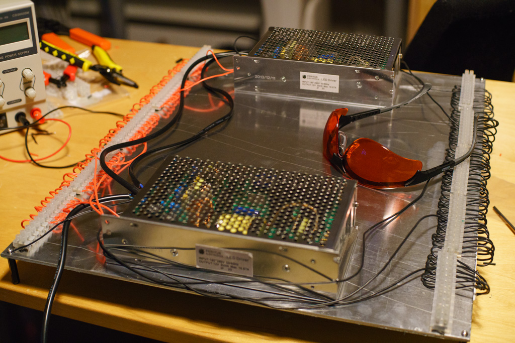
Note the UV safety glasses – looking at this light is like looking directly at the sun and without your pupils contracting. You’ll get cataracts eventually as well. I bought these, not the cheapest but with a little more scratch resistance than most.
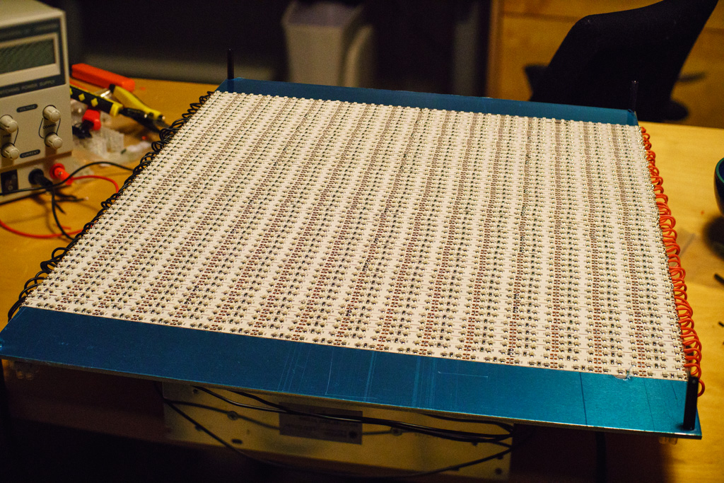
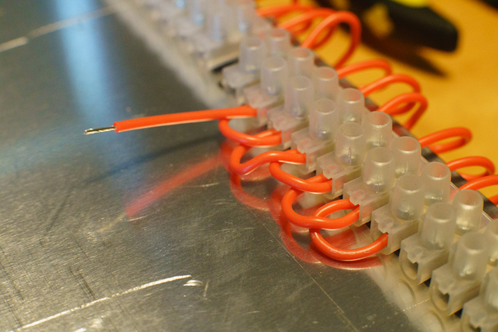
The strips have mounted to sticky tape and can be cut at intervals to make your own sizes. I made my exposure unit 400mm by 500mm so that I could expose just under 16″ by 20″ image area (which would be good on a 20×24 sheet perhaps). Cutting and sticking was fine but after a little research I realised I would have to wire the units in parallel (if you wire them in series you get hot spots from too much current and other problems). This meant attaching wires to each end of every strip and using a connector strip to put them all onto the same voltage. I bought two power supplies as the rating on one was only just enough and I didn’t want things to get hot. The only annoying aspect was soldering the wires to the ends of the LED strips. A good hot soldering iron and pre-tinning the ends of the wires before trying to solder on the LED strips (and pre-tin the strip contacts too). I was very lazy and used strong carpet double sided sticky tape to attach the connection blocks and the power supplies to the aluminium strip.
A couple of spacers on the corners gave me about an inch rise and I was ready for my first exposures! Have a look through the gallery below to see the (fairly ugly) end product. I plan on making a nice box for this once I’ve proven it all works OK.
Top of Unit
Underside of Unit

Soldering
I built a very similar unit a few years ago using the same LED strips and offset every second row so that the LEDs were more evenly spaced. I’m curious how your design works with the neat rows because it does make construction easier and I now want to make a bigger box (I went 11×14) and now want to be able to do larger alternative process prints.
I worked out the spread and optimum distance and it seems you can get away with about an inch away with rows like I have used. You could go a bit closer with offset rows but only by about 20% and I’d rather have a bigger gap anyway so the subject doesn’t get too hot. Just add an inch around the edge and you can offset height of about 2-3 inches I reckon
Soon I will make the same. Nice write with pics.
Thanks!
Hello,
I am currently researching on the subject of LED strip based UV printing devices, and came across this post. I look forward to more posts on the subject.
I ordered some LEDs already, which are on their way from China (only 5m / 600 LEDs for now, I though this would be plenty enough). What are the exposure times that you get with this setup ?
I’m interested in the power aspect of things, and wondering if a reused 12V/3A adapter would fit. I was also thinking using the serial wiring, the same way they are delivered. I will check your links for that.
You mention that the wavelength (around 390nm) is suitable for iron-based process, would it not work with platin/palladium ? I intend to try Callitype also, but there is very little info on the web about LED-based printing.
Anyway, thanks very much for sharing !
Hi there – I’m currently getting between 8 and 15-minute exposures depending on the process. 10 minutes on PtPd is about right I think (PtPd is also an iron-based process as are most of the photographic UV based processes). If you ignore they are LEDs and just an alternative to a metal halide or UV fluorescent tube light source you won’t go far wrong.
Tim, This is exciting. I’ve been interested in this method of printing for a while but have not seen any good resource to build a DIY in UK.